Showing posts with label System Design. Show all posts

Tuesday, July 22, 2025

[Deliveroo] Design Swiggy

Designing a highly scalable food delivery application like Swiggy or Zomato is a complex challenge that involves optimizing for scale, consistency, low latency, and real-time tracking. These apps handle millions of users, orders, and real-time delivery updates across cities, all while ensuring a seamless user experience.

In this post, I’ll walk through a step-by-step architectural design of a food delivery system, starting from functional and non-functional requirements to API design, services, data modeling, and finally addressing performance, availability, and consistency trade-offs.


Requirements:

1. Functional requirements:

  1. It's an app only system.
  2. Only registered users can order food.
    • Delivery partner registration is manual and out of scope
  3. User and delivery partners need to login to order food and deliver food.
  4. Delivery partners need to make themselves available to receive the delivery order.
  5. Restuarants need to register and upload the menu to receive the food order.
  6. Restaurants need to make themselves available to receive the order.
  7. We need to minimize the:
    • Wait time for the users
    • Distance / Time for delivery partners to deliver the food.
  8. User should be able to search the dishes, cuisines and restaurants.
  9. User should be able to see the top rated nearby restaurants on home page.
  10. Collect payment information from user.
  11. Collect bank information from restaurant to pay them
  12. Delivery Partner should be able to mark the order state like in transit, delivered
  13. Users should be able to track their order.
  14. Users should be able to rate restaurants and delivery partners.

2. Non functional requirements:

  1. Scalability
    • 100 M total users.
      • 10 M daily orders. ~ 115 orders / seconds or 1000 - 2000/second during peak hours.
    • 100 K delivery partners
    • Collect delivery partner's location every 5 seconds i.e. 20 K messages / second.
    • 300 K total restaurants
    • 100 items per restaurant menu so total menu items are 30 M.
  2.  Availability
    • 99.99 or higher
  3. Performance
    • Search < 200 ms
    • Loading home screen < 500 ms
    • Loading Menu < 500 ms
  4. CP over AP
    • Consistency is imporant over availability here. 
    • Can't have older menu or older addresses etc.

Design:

Step 1: API design:

As usual, for the api design let's first translate our functional requirements in a sequence diagram which should look like follows:


Given the sequence diagram, we can see the need of having a bidirection connection between server & delivery partners and also server & users.

We now have clear APIs:

Restaurants:

  • POST /restaurants
  • GET /restaurants
  • GET /restaurants/{restaurant_id}
  • PUT /restaurants/{restaurant_id}
  • POST /restaurants/login
  • POST /restaurants/{restaurant_id}/menu
  • GET /restaurants/{restaurant_id}/menu
  • POST /restaurants/{restaurant_id}/join
  • POST /restaurants/{restaurant_id}/state
Delivery Partners:
  • POST /dpartners/login
  • POST /dpartners/{partner_id}/state
  • POST /dpartners/{partner_id}/location
  • POST /dpartners/{partner_id}/rate
Users:
  • POST /users
  • POST /users/login
  • PUT /users/<user_id>
  • GET /users/<user_id>
Order:
  • POST /orders
  • GET /orders?restaurant_id=<id>
  • GET /orders?partner_id=<id>
  • GET /orders?user_id=<id>
  • POST /orders/{order_id>/state
  • GET /orders/{order_id>
Search:
  • GET /search/restaurants
  • GET /search/dishes


Step 2: Mapping functional requirments to architectural diagram:

1. User need to register and login to order food, Should be able to update the info

We will have a User service to serve these two requirements. we can collect the payment info while registeration. User service will use a SQL DB which will have two tables:

  1. User:
    • user_id
    • user_name
    • password
  2. User_Profile:
    • user_id
    • phone_no
    • email
    • address
    • PIN

User Payment information will be sent to another service that is Payment service from User Service. This service will have its own SQL DB which will have following table:

  1. UserPaymentInfo:
    • user_id
    • credit_card
    • billing_address


2. Restaurant registration, login, upload menu and update these details:

We will have a separate service say Restaurant Service which will have its own SQL DB. It will have following tables:

  1. Restaurants
    • id
    • user_name
    • password
    • name
    • location
    • address
    • pin
    • IsActive
    • menu_id
    • avg_rating
    • num_rating
  2. RestaurantMenu
    • id
    • restaurant_id
    • name
  3. RestaurantMenuItem
    • id
    • menu_id
    • item_id
    • price
    • IsAvailable
    • avg_rating
    • num_rating
  4. MenuItem
    • id
    • Name
    • Description
The payment info will be sent to Payment Service to store the bank details. Payment Service will have another table in its SQL DB to store this info:
  1. RestaurantPaymentInfo
    • restaurant_id
    • bank_details
The menu and restaurant metadata will be sent to a new Search service. Search service will store this metadata in it's Elastic Search database.

3. Restaurants need to make themselves available to receive the order.:

Restaurant admin simply call Restarant service. Restaurant service will mark the restaurant's IsActive as True. The diagram for both 2 and 3 FRs is as below:


4. Delivery Partners need to login and make themeselves available to recieve the orders:

To support delivery partners, we will have another service say DPartner Service. This has its own SQL DB to store the delivery partners info. Here are the tables:

  1. DeliveryPartner 
    • id
    • name
    • user_name
    • password
    • rating
    • is_active
    • num_deliveries

Deliver Partners can make themselves available using DPartner Service. It will just change the state in the DeliveryPartner table. Once they made themselves available, DPartner service will create a bidireactional connection using web socket. This will have following benefits:

  • Delivery Partners need to send location very frequently so it will remove the overhead of TCP connection every time.
  • Server can also push messages like pick_up order etc. 

To record these location we will use a new service say Location Service. DPartner service will continue to queue these locations to Location service. We will use a write performant LSM tree based NoSQL DB to store these locations updates. This will contain partner_id and location like lat and long and we continue to update this record until the partner is active. Here is the schema of the collection:

  • partner_id
  • latitude
  • longitude
  • order_id

We are going to have another service say ConnectionManager Service. It will store user_id and connection_id in a highly performant KeyValue pair DB like redis so once the WSS connection is established, DPartner service will call ConnectionManager service to store this info. For now it is not required but it will be required when server push some mesage to delivery partner or user to know which connection to use.


5. When user order the food, system assign the best possible Delivery Partner:

As mention in the functional requirement, user should get the order in minimum time and delivery partner must travel as less as possible.

To order the food, we will have a new service say Order service. Order service will have its own SQL DB. Here are the tables:

  1. Order
    • id
    • user_id
    • restaurant_id
    • payment_id
    • dpartner_id
  2. OrderDetails:
    • order_id
    • restaurant_menu_item_id

For the order to complete, the payment will be done using Payment Service. Payment Service will connect with credit card company and restaurant's bank to complete the payment using third party payment service.

Once the payment is done, order service queue the message to Notification service and Notification service push the notification to Retaurant. Restaurant then fetch the order details from order service and set the state of order as approved by calling Order Service API.

To match the delivery partner, we will have a new service Matching Service. Let's see what it does to match the delivery partner to an order. 

  • Matching service send the user's and restaurant's location to Location service
  • Location service finds all the closed available delivery partners by drawing a circle of 2 - 3 KMs. Restaurant could be the center of the circle.
  • Location service now sends the triplet {partner_location, restaurant_location, user_location} to a third party service.
  • Third party service sends the ETA for every every triplet.
  • Location service then send the {partner_id, ETA} to matching service.

Matching service will then match the partner with order based on ETAs and other criterias. Once matched, Matching service will send the Location service {partner_id, order_id} and Location Service will save order_id corresponding to partner_id to indicate that delivery partner is serving an order.

Now Matching Service will send {order_id, partner_id} to Order Service which will update the partner_id corresponding to order_id. 

Once the partner_id is saved, Order Service queue another message with order info like restaurant location, user location and order_id to Notification service which pushes these details to delivery partners. 


6. User should be able to track their orders

Once the User reaches to order tracking page, user app creates an WSS connection with a new service say Order Tracking Service. Here is the flow:

  1. Once the order is confirmed and delivery partner is assigned, it queues the order_info like order_id, user_id, state, dpartner_id etc to Order Tracking Service.
  2. Whenever restaurant update order state using Order Service API, Order Service also queue this order_info to Order Tracking Service.
  3. Location Service when it sees that and order_id is attached the delivery partner id, then it queues the order_id, location to Order Tracking Service.
  4. Order Tracking Service maintains redis cache to store this info. 
  5. When user creates an WSS with Order Tracking Service, it also sends it to Connection Manager Service to store it.
  6. When Order Tracking Service receives any messages, it first checks with Connection Manager to get the connection id and use the connection id to send the update to User. 

So this is architectural diagram for order placement and tracking:


7. Delivery partner should be able to mark the order state:

Delivery partners can simply call Order service to mark the order state. With this, this is the compelet flow of Orders:


8. User should be able to rate delivery partners and restaurants:

For this FR we can have another service say Rating service. It will have its own SQL DB. We can have different tables or we can use the same table for both restaurants and delivery partners with one more column say type but I am going to use different tables.

Both tables have the same schema:

  1. RestaurantRating
    • user_id
    • restaurant_id
    • rating
    • created_at
  2. DPartnerRating
    • user_id
    • dpartner_id
    • rating
    • created_at

In this way we can also restrict same user to rate restaurants or delivery Partners multiple times. Now we also show restaurant's and delivery partner's rating to users. I know we are not handling NFRs for now but I am handling little performance right now. Otherwise to show details of restaurants or partners we need to make 2 calls (restaurant/dpartner and rating). We are going to use timer jobs at Restaurant Service and DPartner Service which will run at scheduled interval say every 1/2/4/8 hours and fetch the data from Rating service using created_at field and then calculate rating and save it in their own DB.


9. User should be able to search restaurants and menu items.

For this we have already a Search Service which is using Elastic Search. Restaurant Service is already pushing the data there on onboarding or updates.


10. User should be able to see the top rated nearby restaurants on home page:

This is little tricky but we will deal with it during NFRs handling for now, you can see we have every data available at Restaurant Service DB and we can fetch this from its DB only and show it to user.


Step 3: Mapping non functional requirments to architectural diagram:

1. Scalability:

For achieving the scalability we need to have multiple instances of each service and also replicas of DBs.

2. Availabilty:

We have already achieved it using multiple instances and replicas of DBs,

3. Performance:

a. Search < 200 ms

For search performance we already are using Elastic search which should serve the purpose. If required we can add additional details like rating, state in the Elasic Search.

b. Home page load < 500 ms

Here we need to show the Top rated nearby restaurants around the user location but as of now it is not possible as we are storing lat and long. 

We can use Geohash here to divide the earch into geo cells. Now these geo cell ids will be stored in the Restaurant DB as per the restaurant's locations. That means we are going to add a new table RestaurantLocation table in the Restaurant DB. Here is the schema:

  • geo_cell_id
  • restaurant_id
  • restaurant_name
  • restaurant_rating

Now the circle which we are drawing centered at User's location can have around 3 or 4 geo cells. Here is how the flow looks like for getting the nearby restaurants:

  • Get the geo cell id as per the user's location.
  • Get all the geo cell ids which is covered by 2 KM radius circle
  • Now the query to DB will be something like SELECT * from Location where geo_cell_ids in [list of geo cells]

To make this query efficient, we can partition this table based on geo_cell_id. 

If it is still required we can cache top restaurnts of geo_cell_ids in the Redis.

* For matching Delivery Partners we will use the same approach of geo hash and a column "geo_hash_id" will be added  to Location DB. Just like what we did in design of uber.

c. Menu load < 500 ms

There are four tables; Restaurants, RestarantMenu, RestaurantMenuItem and MenuItems, we need to join if we want to get the whole menu which is making this very inefficient. What we can do is maintain another table, RestaurantMenuCache which will just have following fields:

  • restaurant_id
  • menu_blob
  • last_updated_at
We can partition based on restaurant_ids but on range based method to make it more efficient.

d. CP over AP

We are already using SQL DB where consistency is required.


In this post, we methodically designed a scalable, consistent, and performant food delivery application from scratch. We identified critical services, database designs, WebSocket communication for real-time updates, and employed techniques like Geohashing for efficient geo-based queries.

We also mapped our non-functional requirements (NFRs) like scalability, performance, availability, and consistency across the architecture, ensuring that the system remains robust even at 100M users and 10M daily orders scale.

This design is a strong foundation. In a real-world scenario, we can extend it further by adding observability, security layers, fallback mechanisms and cost optimizations.

Monday, October 28, 2024

Design Uber

Problem: Design a highly scalable rideshare service.

Requirements:

1. Functional requirements:

  1. Only registered users can request a cab.
    • Driver registration is manual and is out of scope here.
  2. Driver and user needs to login to request and receive the ride.
  3. Driver needs to make himself available to receive the rides.
  4. Each driver can be matched to multiple riders depends on users and the occupancy of the car.
  5. Price of the ride depends on base flat fee, distance and duration.
    • Exact formula is not given and is subject to change
  6. We need to minimize the:
    1. Wait time of users
    2. Distance / Time for drivers to pickup the user.
  7. Collect payment information from users.
  8. Collect bank information of drivers to pay them.
  9. Driver should start/end the trip.
  10. For actual payment process, we can use third party services.


2. Nonfunctional requirements:

  1. Scalability:
    • 100 M to 200 M daily users.
    • 100 K to 200 K drivers.
    • Peak hours support where demand is 10 times of average.
    • Collect driver's location every ~5-10 seconds =~ 3B messages / day
  2. Availability:
    • 99.99% uptime or higher
  3. Performance:
    • Match users with drivers 10 seconds at 99 percentile
  4. AP over CP:
    • Higher availability is required here over consistency.


Design:

Step 1: API Design:

This looks like a very complex system which makes it even more difficult to come up with the all the APIs which are needed for the system to work.

However we will use sequence diagram to make it simple which we are doing in our previous design problems:


Just one thing to notice, given the sequence diagram, we can see the need of having a bidirection connection between server & drivers and also server & riders.

From the sequence diagram we can now have the clear APIs:

Drivers:

  • POST /drivers/login
  • POST /drivers/{driver_id}/join
  • POST /drivers/{driver_id}/location
  • POST /trips/{trip_id}/start
  • POST /trips/{trip_id}/end

Riders:

  • POST /riders/ - Register a rider
  • POST /riders/login
  • POST /rides


Step 2: Mapping functional requirements to architectural diagram:

1. Only registered users can request a cab.

2. Driver and user needs to login to request and receive the ride.

7. Collect payment information from users.

8. Collect Bank information of drivers to pay them.

To serve these requirements 1, 2,  we can have a single User service. User service will have a SQL DB which contains two tables:

Rider: 

  • rider_id
  • username
  • password
  • age
  • image_url

Driver:

  • driver_id
  • username
  • password
  • license
  • vehicle
  • image_url

For the profile image we will store the image in object store and put the image url in DB.

To support requirement 7 and 8, we will have a separate service Payment Service which will have it's own SQL DB. This DB will contain the RiderPaymentInfo table and DriverPaymentInfo table.

RiderPaymentInfo:

  • user_id
  • credit_card
  • billing address

DriverPaymentInfo:

  • driver_id
  • bank_name
  • account_number

This payment service will connect with credit card companies / banks for the payment processing.

Here is how our architectural diagram looks like:


3. Driver needs to make himself available to receive the rides:

For this Driver needs to call join API and keep sending it's location. We need to have a new service say Driver Service which will create a bidirection connection using web sockets when Driver call the join API. This will have following benefits:

  • Driver needs to send location very frequently so it will remove the overhead of TCP connection every time.
  • Server can also push message to driver such as pick_up rider etc.

To record these location we will use a new service say Location Service. Driver service will continue to queue these locations to Location service. We will use a write performant LSM tree based NoSQL DB to store these locations updates. This will contain driver_id and location like lat and long and we continue to update this record until the driver is booked for a trip.


6. Rider can request the ride and the driver must be matched with minimum wait time:

4. Each driver can be matched to multiple riders depends on users and the occupancy of the car:

To request a ride, we will have a new service called Rider Service. Upon requesting the ride, a bidirectional websocket connection has been stablished between rider and this service as we need to send the updates to the riders. 

To match a rider to a driver we will have a new service Matching Service. Let's double click into this matching service to see how to match a driver.

First approach which directly comes into our mind is simple:

  • Take the lat, long of rider. 
  • Draw a circle centered at rider's location of radius of 2-3 KM and try to find drives within this circle
  • Given the location of drivers is already present in Location Service DB, we can use this DB to get the list of drivers.
  • Take the driver with the least distance.

However the direct distance of two points is not good measure because of road structures, traffic etc.

Given that the ETA calculation is complex and is not our functional requirement, we can use a third party ETA calculation service. With this third party service here is how our flow changes:

  • Matching service sends the rider location to Location service.
  • Location service finds all the closed drivers as per our previous approach of 2-3 KM radius circle.
  • Location service now sends the list of pairs {user location, driver location} to third party service.
  • Third party service sends the ETA of every pair of locations to Location service.
  • Location service send these pairs {driver_id, ETA} back to Matching service to make the final decision.

There are few considerations for matching the driver based on that we can match the driver:

  • Match driver with the lowest ETA
  • Math the driver who is about to finish the trip nearby rider.
  • Allow multiple riders to share a ride
  • Prioritize drivers whose rating is high for high rated rider.
  • Permium service
  • Prioritize drivers who have earned very less.

Once the Matching service matches the driver, it needs to store this info somewhere. For this we will have new service say Trip service with it's own SQL DB which will contain source and destination, user_id, driver_id, fare, start_time, end_time, distance etc. Here are the next set of steps: 

  • Create a new Trip using the Trip service. Get the trip_id in response.
  • Send the signal to Location service to tell it that Driver is booked. It will also send the trip_info. The trip_info will contain trip_id and rider_id for sure.
  • Location service will add two new columns: Driver state and Trip Info. 
  • Matching service now send the trip info and driver details including location to Rider service which will push this info to Rider.
  • Similarly Matching service send the trip info and rider details including location to Driver service which will push this info to driver
  • Now when driver send the location to Driver service, Location service append this record to it's DB and also send this location update to Rider service which will update the rider.

You can see how much this web socket connection is useful in these scenarios.


9. Driver should start/end the trip:

Upon reaching the source/destination or where the user wants a drop, driver will start/end the trip by calling the APIs. This will be redirected to trip service. Now Trip service will notify Location Service to change the status of driver as In_Trip / Free. 

Trip service can get the details of locations from Location Service to calculate the distance and everything else for the payments etc.


5. Price of the ride depends on base flat fee, distance and duration:

10. For actual payment process, we can use third party services:

Let's come to the Post trip part where we need to collect the payment from rider and send driver fee to driver account. We also need to send this info as an Email to rider and driver.

Here is the flow:

  • Trip servivce will calculate the ride cost and driver fee.
  • Trip service will queue the trip_info including user_id, driver_id and payment_info to Payment Service.
  • Payment service will interact with third party service to mak the payment.
  • Once the payment is successful, It will queue two messages; one for user and one for driver including trip info and their corresponding payment_info to new service Notification Service.
  • Notification service will send email to driver and user.


That's all about the functional requirements 


Step 3: Mapping non functional requirements to architectural diagram:

1. Scalability:

Given the traffic we need to run multiple instances of every service. Even the notification service is not public facing service but still at the time of peak, we might need to scale up this service too.

Now the problem is about the Driver service and Rider service as these are having web socket persistent connections. How the location service will come to know which instance to connect to send driver location to rider or how Matching service will know which instance to connect to send trip info to driver.

To solve this issue, we will have a new service called Connection Manager which will have its very efficient key value pair NoSql DB like Redis to maintain this mapping. Now Location Service or Matching Service can query Connection Manager Service to get the right instance.


2. Availability:

For this we just need to add replica of our DBs in order to achieve availability.


3. Performance:

We need to match Rider to Driver with 10 seconds. Let's see what are major steps we have for match:

  1. Get the closest drivers list to the rider.
  2. Get the ETA of these drivers from third party service.
  3. Take the Driver with the lowest ETA.

If you see we can't do anything about step 2 and step 3 is fairly simple. Let's see how we can get the list of closest drivers.

We need to calculate the distance of every free/in_trip driver with the user's location which is fairly expensive. Say somehow we are able to apply certain index on Location DB over Lat and Long (I am not sure how we will use it), it still be very expensive.

Also these floating point calculations are little time consuming for computers. It looks like we won't able to achieve our ETA.

We will use Geohash here to divide the earch into geo cells. Now these geo cell ids will be stored in the Location DB as per the driver locations. That means we are going to add a new column geo_cell_id in the Location DB.

Now the circle which we are drawing centered at User's location can have around 3 or 4 geo cells. Here is how the flow looks like for the step 1 of getting the closes drivers:

  • Get the geo cell id as per the user's location.
  • Get all the geo cell ids which is covered by 2 KM radius circle
  • Now the query to DB will be something like SELECT * from Location where geo_cell_ids in [list of geo cells]

To make the above query we can shard the Location DB based on geo_cell_id or create a hash index over it.

That's all about the performance. Now that we have covered every functional and non function requirements, here is our final architectural diagram:


I know the diagram became a bit messy so I'll improve it later!

Design Youtube

Problem: Design a highly scalable video on demand (VOD) streaming platform.

Requirements:

Before we jump into requirements, we should realize we have two different types of users:

  • Content creators
  • Viewers

If we try to observe how they use our platform, we can see the requirements are different both functional as well as nonfunctional requirements.

1. Functional requirements:

a. Content creators:

  1. Upload any format/codec video.
    • Once the video is uploaded, it can be deleted but not be modified.
  2. Each video should have metadata:
    • Mandatory: title, author, description.
    • Optional: List of categories / tags.
    • Metadata can be updated anytime.
  3. Get an email notification when the video is available publically.
  4. Live streaming is not supported.

b. Viewers:

  1. Only registered users can view the content.
  2. Can search using free text in all of video metadata.
  3. Can watch vidoes on any kind of device (desktop / phone / TV) and network conditions.

2. Nonfunctional requirements:

a. Content creators:

  1. Scalability:
    • Thousands of content creators.
    • Upload 1video/week per creator
    • Average video size ~50 GB (50 TB / week)
  2. Consistency:
    • We prefer to have consistency here over availability.
  3. Availability:
    • 99.9 percentile
  4. Performance:
    • Response time of page load < 500 ms at 99 percentile.
    • Video becomes available to view in hours.

b. Viewers:

  1. Scalability:
    • 100K-200K daily active users
  2. Availability:
    • 99.99 percentile
  3. Performance:
    • Search results and page loads < 500 ms at 99 percentile
    • Zero buffer time for video play


Design:

Step 1: API design:

As usual, for the api design let's first translate our functional requirements in a sequence diagram which should look like follows:


Now we can easily identify the entities and URIs using above sequence diagram:

  • Users
    • /users
  • Videos:
    • /videos
    • /videos/{video_id}
  • Search:
    • /search

Now let's put HTTP method:

  • Users:
    • POST /users: Create / register user
    • POST /users/login: Login a user
  • Videos:
    • POST /videos: Start upload a data
    • PUT /videos/{video_id}/metadata: Create/update metadata of video
    • GET /videos/{video_id}: Get the video url
    • POST /videos/{video_id}/play: Send the video content to client
    • DELETE /videos/{video_id}: Delete a video
  • Search:
    • GET /search


Step 2: Mapping functional requirements to architectural diagram:

a.1 Content creator can upload any format/codec video:

b.3 Viewers can watch video on any device and at different network conditions:

I am taking both of these requirements together as these are inter related. We need to upload any video in such a manner that it can be supported on any device and adapted to different network conditions to view.

Let's first understand what is a video file. 

The video file is a container which contains:

  • Video stream
  • Audio stream
  • Subtitles
  • Metadata like codec, bitrate, resolution, frame rate

The binary representation of these containers like mpg/avi/mp4 can be different based on how these streams are encoded and algos to encode and decode these streams are called codecs like H.264 or AV1 or VP9 etc.

The video captured using a camera is encoded based on lossless compression algorithm which makes it suitable for professional editing but it is too big in size so this kind of codec is not suitable for streaming and storage at scale so the first step is too apply a lossy compression algorirthm. This method of converting a encoded stream to a different encoded stream is called Transcoding.

Size of a video = Bit rate (bits/second) * Video length (seconds)

So this is obvious that we need to reduce the bit rate in order to reduce the size of video but given that we need to support different devices and different network bandwidth. We can't depend on only one bit rate. We need to support multiple outputs file supporting different bit rates which is directly proportonal to resolutions. The standard resolutions are 360p, 640p, 720p, 1080p and 4K.

This will partially take care of supporting multiple devices but it won't support varying network conditions like home network getting used by multiple users or the user is travelling. To support this requirement, we will use technique called Adaptive bit rate or Adaptive streaming.

In Adaptive streaming, we break our stream into multiple small chunks of size say 5 seconds or 10 seconds. We put references to all of these streams in a text file called manifest(mpd). When player tries to play the video. It first download this manifest file and then choose a default resolution (say 720p) and play it's say first 4-5 chunks to analyze how the network conditions are. If the network conditions are better it switches to better resolution say 1080p or even 4K. It there are download delays then it goes for lesser resolution chunks. Player keeps analysing the chunks download speed to decide which resolution to go for.

The next step is to fully support every kind of devices. For this we need to package our video content to support different streaming protocols. Different OS / browser supports different protocols. Here we can also apply DRM(Digital Rights Management) to protect our video in order to support FR# b.1 Only registered users can watch the video. Using DRM we can also support subscrption when we want to intoduce it.

Now if you see there are steps which we need to take in order to upload the video and making it available for different devices and different locations / network bandwidth. We will use pipes and filter pattern here to support it. 

We will have a Video service as public interface for this whole activity. This service will have it's own DB which is NoSql DB in order to support fluid schema. So here is the flow of video upload:

  1. Content creator call Video service to upload video.
  2. Video service will start the upload to object store asynchronously and save the metadata into it's DB and return the confirmation to user with video id.
  3. Once the video upload is complete to object store, it queues this message to a new service Transcoding service.
  4. Transcoding service first convert this video to 5-10 seconds chunks and transcode each chunk into multiple resolution and upload it into it's object store. It also generates manifest file for adaptive streaming.
  5. Transcoding service now queue the message to new service say Packaging service.
  6. Packaging service package these streams according to streaming protocols and save it into it's own object store.
  7. Package service now queue the video_id and video_url(which is ultimately manifest download) back to Video service and video service updates it's DB using the video_id.  

We can debate over a point on Transcoding service where we can propose a new service to break the uncompressed video in chunks, queue these chunks to let transcoding service just transcode these chunks in parallel. But that's what we can achieve using multithreading in the transcoding service itself. In that way it will be much easiser to debug issues and also much easier to support the restartabilty as all these chunkings and transcoding will happen in just one service.

We can support FR# a.3 Notify creatore when video is publically available here only by adding a new service say Notification service. Video service will queue the video details to this service. Notification service now can send the notification (email) to content creator.

With this knowlege let's see how our architectural diagram looks like.


a.2 Update the video metadata:

a.1 Delete the video:

User can simply call the video service to perform these opeations so now here is how the diagram looks like


b.2 Viewer can search for the video against the video metadata:

To support search we need to have a different service say Search service whose DB is optimized for search like Elastic search. Video service can queue the metadata to this service so you can assume it will also become the part of video upload / update of metdata / deletion of metadata. 

We also need to use pagination here.


b.3. Watch video on any device:

We have already done enough to support this requirement. Client first need to call Video service to get the video_url. Client then downloads the manifest file and then client/player will directly stream the chunks of video from object store as per adaptive streaming which I have already explained.


 So now we are done with every functional requirement we have.


Step 3: Mapping non functional requirements to architectural diagram:

a.1 Content creator scalability:

There is not much to do in terms scalability for the first scalability requirement as the frequency of video upload is not much (1/week/user) That means ~10K video uploads in a week. However it can happen that at a particular time we can get thousands of upload requests. To support those we can have multiple instances of Video service and Web app service. 

To tackle the video size we have already created a pipeline to compress the video size but there is still one problem; 

If we take the whole video content to first video service and then upload it to object store, this whole process will consume lot's of resources and as it can take hours to upload uncompressed video, we might end up scaling video service too much. 

To resolve the problem we can use presigned urls of object store. Presigned urls are the urls with limited permissions and limited time. With presigned urls, the flow of video upload looks like as below:

  1. Client send request for video upload to video service.
  2. Video service requests presigned url from object store with it's own permissions.
  3. Send the presigned url as response of video upload API to the client.
  4. Client now directly upload the video to object store using presigned url. 
  5. Rest of the pipeline remains same.

With this flow, we can see Video service doesn't have to scale and we will save lot's of resources so now with these changes here is how architecture diagram looks like:


a.2 Content creator availability:

We have already take care of the availabity using the multiple instances of web app and video services. We can use the cloud native services for video transcoding and packaging like AWS Elemental MediaConvert and AWS Elemental MediaPackage to support the availability.

We can replicate the Video service DB to support the availability.


a.3 Content Creator Performance:

We have already taken care of the performance as there is not much to do. However the only problem is when all/many content creators try to upload videos at the same time. In such scenario, we might not able to complete the video upload pipeline in hours. 

We need to parallelize this process. That means we need to have multiple instances of Transcoding service and Packaging service.


a.4 Content Creator CP over AP:

To achieve this we just need to choose the right Video service DB or DB's configuration which supports consistency over availability. That's all!


b.1 Viewers Scalability:

To support this 100K - 200K user visits we have already scale our web app service and video service but to scale the search functionality, we need to have multiple instances of search service. This will take care of the scalabilty of service. 

As elastic search is not cloud native, we can use AWS opensearch / Elastic cloud on AWS which autoscale itself.


b.2 Viewers Availability: 

We have done mostly everything for the availability but as here our availability requirement is high. We can use muti region deployment and a global load balancer too. This will also help with the performance.


b.3. Viewers Performance:

We are using adaptive bitrate streaming for the zero buffer time but as you see still we need to download intial chunks, we need to go to object store which might be expensive so we can use CDN to provide it. We can have initial chunks in the CDN to increase the performance of download and then the client can use adaptive streaming to go for the right chunks.

Please note that we can put the whole video too on the CDN which will definitely improve the performance and the quality of the video but it can be very expensive so I am still opting for initial chunks of videos.


b.4. Viewer AP over CP:

We are already using lot's of async operations / message broker which guarantees availability but eventual consistency. For search we are already receiving metadata updates using queue and also Elastic search provides AP over CP so this requirement is already satisfied.


With this we are done with every functional and non functional requirements and here is how our final architectural diagram looks like:


That's all!

* Please note that here we should have a User service to support user login and registration but that's very obvious so I have not discussed it here. Given the user's volume is in hundreds of thousand, we don't need to do many things.

Friday, October 18, 2024

Design Instagram

Problem: Design highly scalabale image sharing social media platform like instagram.

Requirements:

1. Functional Requirements:

  1. Only registered user can access the platform. They need to provide following info while registering:
    • Mandatory: first name, last name, email, phone number, profile image, password
    • Optional: age, sex, location, interests etc.
  2. User can share/post only images
    • We need to design it in a way to extend it to videos or text.
  3. Search a user using different attibutes
  4. Unidirectional relationship: User A follows User B does not mean User B also follows User A.
  5. Load a timeline of latest images posted by people they follow sorted by recency in descending order
 

2. Non-functional Requirements:

  1. Scalability:
    • ~1-2 billion active users
    • 100-500 million visits / day
    • Each user uploads ~1 image / day
    • Each image size ~2 MB.
    • Data processing volume: ~1 PB / day
  2. Availability: Prioritize availability over consistency as it is okay even if user does not see the latest data. We are targetting 99.99% here.
  3.  Performance: 
    • Response time < 500 ms at 99 percentile.
    • Timeline load time <1000 ms at 99 percentile.


Design:

Step 1: API design:

For the api design, let's first translate our functional requirements in a sequence diagram which should look like follows:


Now if you see above, we can easily identify the entities and URIs:

  • Users
    • /users
    • /users/{user-id}
  • Images
    • /images
    • /images/{image-id}
  • Search
    • /search
Now let's put HTTP methods:

  • Users 
    • POST /users - Create user / register user
    • POST /users/login - Login a user
    • POST /users/{user-id}/follow - Follow a user
    • DELETE /users/{user-id}/follow - Unfollow a user
    • GET /users/{user-id}/timeline - Get user time line. This requires pagination.
  • Images
    • POST /images - Post an image
    • GET /images/{image-id} - Get an image
  • Search
    • Get /search - Search a user


Step 2: Mapping functional requirements to architectural diagram:

Before we move to our main functional requirements, I want to add a service say "Web app service" to serve the html pages since we have support on desktop web browser too.

1. Registering user to our platform:

We will have a User service with it's own DB which will help with login and registration of users. User service database will have following fields as per FR#1:

  • user_id
  • user_name
  • first_name
  • last_name
  • email
  • password
  • phone_number
  • profie_image_url
  • and some optional fields like age, sex, interests, location etc.
If you see we have so many optional fields which can change with time like some optional fields can be removed and some can be added. That means our schema is fluid and that's why we are going with NoSql Document DB. Given we have around ~1-2 billions users, these schma changes become an considerable overhead.

In the schema we are storing the profile image url instead of profile image because DBs are not optimized for blob storage so what we will do is we will store the profile image into a blob store or object store and then save the image url in our DB.

Once the registration is completed, client will get user id and auth token which will help client with further operations.


2. Post an image:

Let's have a post service for this service, we are not calling it as image service so that we can extend it to any type of post. This service will have it's own DB which contains the following fields:

  • post_id
  • user_id
  • post_url
  • timestamp
  • post_type - This will be by default image but can be extended to video etc.
Since this is a fixed schema, I am going to use SQL DB for storing this info. Here is the flow of image upload:
  1. User send the request to Post service to share an image
  2. Post service send the image to object store
  3. Object store return the url of uploaded image
  4. Save the image metdata and url in the DB
  5. Return confirmation to user.


3. Search users using different attributes:

We can use the same user service to search the users but if you see this DB is not optimized for search As we don't know in advance what all the attributes are searchable or what kind of search we are going to support, it's better if we use a different service say Search service with DB which is optimized for search scenario like elastic search or other lucene based DB.

So now whenever there is a new user added or there is an update in user's record we can queue it to the search service. Search service will updates it's DB. 


4.: Follow/Unfollow user:

We can create another service to handle follow/unfollow activity but for me it's not that much useful and is unnecessary. We can use existing User service only, we just need to create another collection with following fields:

  1. follower_user_id
  2. target_user_id 
  3. target_user_name


5. Loading the timeline of the user:

That's the most complex problem. Within the current design here is how we can achieve it.

  • Client send the request to User service
  • User service gets all the users who the user is following.
  • It will then query the posts of all the users sorted by timestamps with pagesize of 20-50 using the Post service.
  • Send page size number of posts sorted based on timestamp to the client.
  • Client can then dowload the images using the post_urls from object store.
This will definitely solve the problem but it is very inefficient. I know we are not solving the non-functional requirements now but we should think about the performance.

To make it efficient, we will use CQRS pattern. We will have a new service called Timeline service. This will have an efficient key value pair DB where key is the user_id and value is the list of post records of all the users followed by the user with user_id(key). Every post record will have {post_url, user_id, timestamp}

Now here is what we do with this new service:

  • POST service will queue the new posts containing post_url, user_id, timestamp to Timeline service.
  • Timeline service will take the user_id and get it's followers from User service.
  • It then add this post to the front of all the followers' list of post records. It can remove the posts if the list is have more records than what we need to show in the timeline.
With this new service, our flow of showing timeline will become straight forward:
  • Client requests Timeline service for the timeline.
  • Timeline service returns the list of post records from it's key value db with key as requested user's user_id.
  • Now client can download the images from object store using post_url.
This will be eventual consistent but that's okay as per our non functional requirements. This will be much efficient than the older design.


Step 3: Mapping nonfunctional requirements to architectural diagram:


1. Scalability: 

If you see we have following scalability requirements here:

  • Number of users: We have 1-2 billion users data which will be huge so we can't rely on just one DB instance so we have to shard the User service DB. We can shard using hashing technique:
    • User DB: Shard on the basis of user_id.
    • Follower DB: Shard based on target_user_id as our main case is to get the followers which is a call from Timeline service.
  • For search we are already using elastic search and we can shard it too.
  • Number of visists: To support these number of visits, we have to run multiple instances of different services behind load balancer.
  • Number of posts: This has two parts:
    1. Data in the DB: This will be huge also so we have to shard Post DB as well as Timeline DB. Post DB can be sharded using post_id and Timeline DB using user_id.
    2. Image Data: As per requirement we need to save petabytes of data because we are getting uncompressed image. Not only these images will take lots of space but also these are not optimized for viewing on Mobile device or browser. We can introduce an async image processing pipeline like AWS severless image handler to compress these images which will convert this petabytes of data into TBs or even GBs.


2. Availability:

By using multiple instances of our services behind load balancer, we have almost achieved the availability. We can have replicas of our DBs to achieve the availability requirements. Additionally we can do multi region deployement and have a global load balancer in case one region is down. It will also increase the performance.


3. Performance:

We have two performance benchmarks:

  • 500 ms for every page load: To achieve it we can use CDNs to store html pages, CSS and post images.
  • 1 second for timeline page load: We have already made a decision to use CQRS pattern and made Timeline service to serve the timeline page. This will take care of the performance part but it will create a different problem. There are few thousands of users whom we call celebrity / influencers and millions of users follow them. In case if a celebrity user makes a post, millions of entries of Timeline service DB will be updated which might slow down the DB and hence the performance. To tackle this situation we can make following steps:
    1. Define which user is celebrity; Say a celebrity has 1 M followers.
    2. Make a column in User DB - IsCelebrity which will tell if the user is a celebrity or not.
    3. When celebrity post an image and Timeline serivec calls User service to get the followers list. Instead of returning followers list, User service will return IsCelebrity = true.
    4. Another Key-Value pair say Celebrity POST DB will be added to Timeline service DB which where key is celebrity_user_id and value is sorted list of post records.
    5. When Timeline service receive IsCelebrity as true. It just add the post into Celebrity POST DB.
    6. While loading the Timeline, Time line service get the list of celebrities from User service which the user is following using new REST endpoint on User service say GET /users/{user-id}/celebrity.
    7. Timeline service then merge the sorted results it gets from celebrity key value pair and user key value pair and returns it to user.
And that's all about the performance. Now that we have addresses every requirement functional or non functional, here is our final architecture diagram:


Have fun!


Thursday, August 15, 2024

Design Stack overflow

Problem: Design a highly scalable public discussion forum like reddit, quora or Stack Overflow. Here are the features that needs to be supported:

  • Post questions / news to public
  • Comments on existing posts
  • Upvote/downvote posts or comments
  • Feed of most popular posts.


Requirements:

Functional requirements:

  1. This is browser only application.
  2. A logged in user only can post, comment and vote.
  3. A post contains following:
    • Title
    • Tags
    • Body containing text and image
  4. Any user (logged in) can comment on any post.
  5. Comments are shown as list in descending order by time.
  6. Use can delete his/her own comments or posts.
  7. Any user can vote any post or comment.
  8. A user's home page contains the top popular posts in the last 24 hours where:
    • Popularity = Upvotes - Downvotes

Non functional requirements:

  1. Scalabilty: Millions of daily users.
  2. Performance: 500 ms response time 99 percentile.
  3. Availability: Priority to availability over consistency as it is ok if the user won't see the latest data.
  4. Durability: Have posts and comments till the user doesn't delete it.


Design: Now that the requirements are clear. We will start with our design. 

Step 1:  API design:

We will first try to come up with the Rest APIs as per our functional requirements. For this we need to first identify what are the entities in our system and try to map those to URIs

  • Users: 
    • /users
    • /users/{user-id}
  • Posts:
    • /posts
    • /posts/{post-id}
  • Images
    • /posts/{post-id}/images
    • /posts/{post-id}/images/{image-id}
    • /posts/{post-id}/comments/{comment-id}/images
    • /posts/{post-id}/comments/{comment-id}/images/{image-id}
  • Comments
    • /posts/{post-id}/comments
    • /posts/{post-id}/images/{comment-id}
  • Votes
    • /posts/{post-id}/vote
    • /posts/{post-id}/comments/{comment-id}/vote
Let's see how the post looks like: (response of GET)

{
    post_id: string
    title: string
    tags: List of strings
    user_id: string
    upvotes: int
    downvotes: int
    body: json
}

Let's see how the comment looks like: (response of GET):

{
    post_id: string
    comment_id: string
    body: json
    user_id:
    upvotes: int
    downvotes: int
}

Now that we know the entities and URIs, its time to assign the HTTP method which wll ultimately results ino our final APIs:
  • Users:
    • POST /users/ - Create/signup a new user
    • POST /users/login - Login a user
  • Posts:
    • POST /posts - Create a new post 
    • GET /posts - View posts. Response of this requires pagination as it can contain even 1 million posts so the parameters can be:
      • limit
      • offset
      • user_id (optional)
    • GET /posts/post-id - View a post
    • DELETE /posts/post-id - Delete a post
  • Comments:
    • POST /posts/{post-id}/comments - Create new comment
    • GET /posts/{post-id}/comments - View post's list of comments
    • GET /posts/{post-id}/comment/{comment-id} - View a comment
    • DELETE /posts/{post-id}/comment/{comment-id} - Delete a comment
  • Votes:
    • POST /posts/{post-id}/vote - Upvote/downvote a post
    • POST /posts/{post-id}/comments/{comment-id}/vote - Upvote/downvote a comment
  • Images:
    • POST /posts/{post-id}/images - Upload a image to a post body
    • GET /posts/{post-id}/images/{image-id} - Get an image of post
    • POST /posts/{post-id}/comments/{comment-id}/images - Upload a image to a comment body
    • GET /posts/{post-id}/comments/{comment-id}/images/{image-id} - Get an image of a comment

Step 2: Mapping functional requirements to architectural diagram:

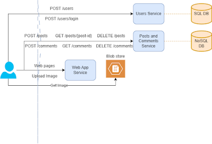
1. Browser only application: For this we will have web app service which will serve static web pages.


2. User Sign up / login: We will have a user service and this service have its own DB to store user info which we can choose as SQL DB as it's going to be structured data and also its not going to be huge.


3.  Create/Delete a post: Again for this we will have another microservice say post service which will have it's own DB. As these number of posts are going to be huge and also post schema, we may want to vary time to time, I am going to use Nosql DB for this.

Given we can upload an image in the post, we can use any blob store to save the imges so if the post contains the image, a request will go to web app service which will upload the image to blob store and then take the image-id and put it in the post body and send a request posts service to save the post

While viewing the post, first we will get the post content using the posts service and then when the browser sees the image url, it can directly fetch from the blob store using the url.


4. Posting comments / Deleting comments: 
5. Comments are shown in list in descending order of posting time:
We can use a different microservice Comments with it's own DB but we can merge it with Post service and use the same DB. As you see comments are tightly attached to post and also their schema is almost same except comments will have a post id attached to it. We also need to add a timestamp fields as we need to show comments in sorted order.

We can opt for any approach but I am choosing to have one micro service for posts and comments and calling it Post and Comment service.

If you see we are also satisfying FR 6: Deleting posts and comments here.


7. Upvote or downvote a post or comment: For this functionality, we will have a different service say Votes service with its on DB. Now we have a choice here:

We can just maintain a schema like folllows:

Post Id 

count

Comment Id 

count 


But the problem with the above schema is 
  • We can't restrict user to just vote once for a single post/comment.
  • FR 7: Can't get popular posts of last 24 hours.
That means we can't go wth the above schema. Hence here is the schema which I am proposing:

Post_id 

User_id 

Vote (+1 / -1) 

Timestamp 

Comment_id 

User_id 

Vote (+1 / -1) 

Timestamp 


With this we can at least achieve the functinalties including FR 7 too. We will see the performance part when we will address non functional requirements. 


8: Home page contains the top popular posts: This is the most trickest functional requirement of this design. If you see the voting data is with Votes service and post content is with Posts service. Getting popular posts when the api call has been made could be very expensive. As this list is there in the home page, we can't risk of having delays in the page load.

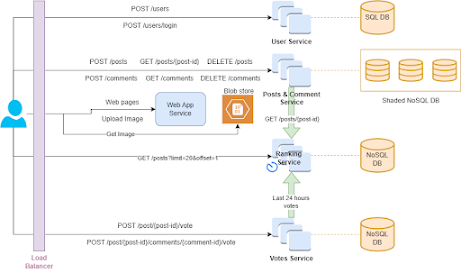
To solve this issue we are going to use CQRS pattern. We are now going to introduce a Ranking microservice which will pull voting data from Votes service and post content from Post service. It then sort this data based on ranking and save this data into its own nosql DB. Now whenever the call for popular posts comes, it will be redirected to ranking service.

There are some consideration here:
  • We know that the sliding window here is 24 hours so rankng service can query only the posts which are kind of active in this window.
  • Given we don't have to show always the most recent data, we can use batch processing in the ranking service as this operation is heavy.
So here is what ranking service will do at a regular interval:
  • Get the active votes from voting service for last 24 hours.
  • Group the votes (upvotes - downvotes) by post_id. 
  • Sort the post_ids in descending order according to votes.
  • Get the post content from POST service.
  • Save it in the DB.


So above is the final design of our product which is satisfying all the functional requirements. Now let's move to non functional requirements.


Step 3: Mapping non functional requirements to architectural diagram: 

1. Scalablity: Given we are talkng about millions of active users, a single instance of service won't work. Obviously we need to have multiple instances of every services and a load balancer to balance the traffic.

Another scalability issue here is the large data of posts and comments so we are going to shard the Post and comments data.

For posts we can use hash based sharding with hashing on post_id. I know this can be a bottlenect if we have to show all the posts from a particular user as posts might be distributed among multiple shards but this is not even our functional requirement. If it is added then we can still serve it and with little tweaks we can serve it effficiently.

For comments we can't shard based on comment_id as in general the comments will be fetched according to post_id and if you see if we go with comment_id, we might end up retrieving comments from different shards which is a big performance issue. 

So what we can do is we can shard the comments based on post_id using hash based sharding. This will work well but it will create problem when a post become popular it starts having too many comments then what will happen that a particular shard will become too big and can become the scalability issue and also performance bottleneck.

To handle such issue we can use a compound key (post_id, comment_id) and we can apply range based sharding. If we use it, mostly we will get data from one shard or at most two shards.

In this way we can handle the scalability.


2. Performance: There are multiple ways to make this system performant.
  • Image load time can be greater while fetching from the blob store. To avoid that we can use CDNs where we can store images of popular posts. We can also use CDNs to serve the static html pages too.
  • We can use cache to store the most popular posts and it's content in order to avoid traffic on GET requests of posts which are ultimately be directed to Posts service or Ranking service. Even the cache is not up to date, it is fine as we have chosen availability over consistency so eventual consistency is just fine.
  • Index on post_id for post collection and compound index(post_id, comment_id) on comment collection really can help on speeding up the Get requests. We can do the similar indexing on other DBs too.
  • Now another problem is, for a post/comment to load, we also need to show the upvotes and downvotes of the post or comment but votes data are there in Votes service DB so to load the post we need to call two microservice. We can take following steps to make it faster to fetch all post data or comment data including votes from one microservice only:
    • Two fields will be added to post and comments collection schema:
      • upvotes_count
      • downvotes_count
    • Queue the voting event from Votes service to Posts service so post service worker will fetch the events and can bulk update the DB with upvotes and downvotes count.
I think we are good with the performance point of view and now our system looks like following:


3. Availability: To achieve the availability we can replicate the databases and our services. We can also have our system running and replicated in different regions. This will also boost the performance.

4. Durability: We are already achiving the durability when we replicated the data accross regions. We can still periodically backed up our data to cheaper storage like S3 in order to have backups. This can also help us to cleanup old data from DBs to boost the performance if required.

Now that we have handled our every functional and non function requirements. Here is our final design:


That's all for this system design problem!